THE SAVING OF THE PEGGY By Fred Crowell
A SHORT HISTORY OF THE COBLE.
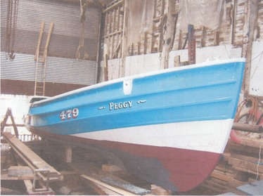
NAME PEGGY.
REGISTRATION NO. BK 7.
BUILT 1924,
BUILDER HARRISON, OF AMBLE,
FIRST OWNER MR. ROBERT RUTTER
FIRST PORT LOCATION. SEAHOUSES.
SECOND OWNER MR. ERIC GREGORY. WHO LIVED AT BEADNELL
THIRD OWNER. MR. ROBERT ROBINSON,
BOAT NOW MOVED TO AMBLE, AND GIVEN NEW NAME.
NEW NAME GLAD TIDINGS.
NEW REGISTRATION NO. BH 177
A GAP IN INFORMATION AS TO WHEREABOUTS.
NEXT KNOWN OWNER HARTLEPOOL
BOAT BOUGHT FROM THERE BY MR. M DAWSON APPROX 2003
Page 2.
WITH GRATITUDE FOR THEIR HELP DURING REPAIRS.
OWNER MICK DAWSON AND SON TIM
MR PETER WEIGHTMAN HISTORIC ADVICE ON COBLES
ANDREW AT GREYTHWAITS SAWMILLS WINDERMERE
SEAWARE Ltd AT PENRYN CORNWALL
FOR MARINE SUPPLIES AND FITTINGS
WILLIAMSON’S PAINTS OF SUNDERLAND
M H SOUTHERN TIMBER IMPORTERS JARROW
Page 3.
“THE SAVING OF THE PEGGY”
THE FOLLOWING STORY ABOUT THE PEGGY IS HOPEFULLY
ENTERTAINING BUT MOST OF ALL A HELPFUL AND USEFUL
GUIDE TO ANY PERSON TAKING UP THE CHALLENGE OF
COBLE RESTORATION
FRED CROWELL BOATBUILDER
STARTED TO WORK AT ROBSONS BOATBUILDERS
SOUTH SHIELDS. AUGUST 1962
COMPLETED 5 YEAR APPRENTICESHIP
STAYED EMPLOYED TILL SEPTEMBER I98O
LEAVING TO START OWN BUSINESS AS BOATBUILDER
WORKING FROM THE BOATHOUSE WITH SLIPWAY IN WAPPING STREET
THIS WAS PREVIOUSLY USED BY THE TYNE PILOT’S TO REPAIR THEIR WOODEN VESSELS. BUT GAVE IT UP WHEN THEY MOVED TO LARGER FIBREGLASS VESSELS TO ATTEND SHIPPING ENTERING, LEAVING THE TYNE
BUSINESS RAN UNTIL 2015 WHEN HE RETIRED AT 68 YEARS OLD HAVING
REPAIRED MANY BOATS AND COMPLETED SEVERAL RESTORATIONS
Page 4.
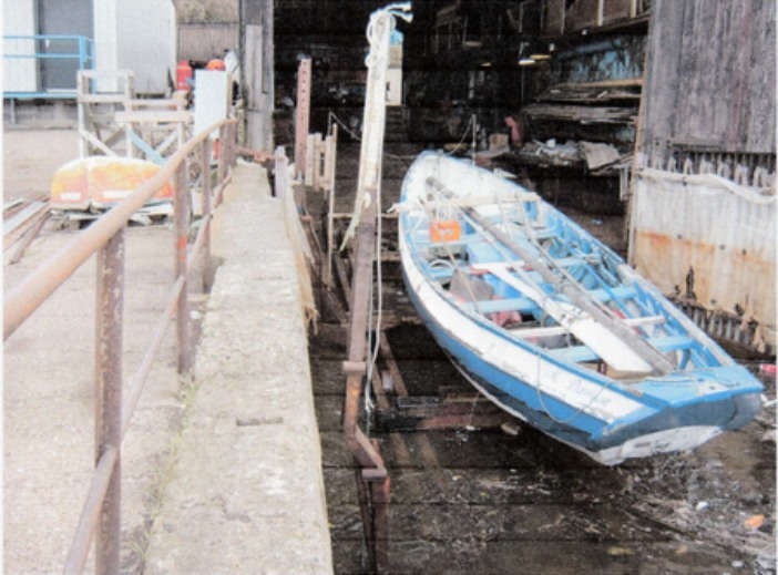
After a long wait the Peggy is finally on the cradle, ready to be pulled into the boathouse. Mick has had the coble lifted in at the boat club down river and towed to the slipway to be placed on the cradle at the high tide.
After standing on blocks in the boat club for the last 4 years, having all of the listons “or landing battens” removed she stayed afloat very well enough for 100 yards tow, any further would have needed some plugging up and magic putty.
Now we start to bring her in, we use 2 lines from the cradle at the front of the cradle to get the boat on the centre, once the stem has landed these lines are dropped while we position the boat aft. Bolted onto the cradle is a timber baulk. This is 16 ins high. This matches the slope on the slipway so the boat settles nice and easy. The advantage of this baulk gives us working space below the boat and a clearance for the propeller and shaft.
She’s now settled on the cradle and clear of the water, you can see the water running out of the missing liston nails but as these planks are to be replaced there is no need to go around with chalk, marking the leaks.
Page 5.
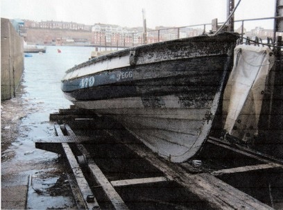
The boat is now hauled clear of the tide and pulled half way into the shed. At this stage we do a pressure wash on the outside. Normally this is to remove weed and barnacles but this time it’s Loose paint. She looks a bit sad as she rolls up the slip.
Mick had started to burn off the paint but only got about 8 feet each Side this resulted in some confusion as he stopped in the middle of the name and the port side read as “eggy” and the starboard side was “Pegg”. Another short haul and its into position to lock off the cradle and slack back on the winch wire.
Next day we remove all the inside gear and loose fittings then remove all the floors. Now it’s bucket and scraper time, this time its not at all to bad, because she ain’t been Fishing or potting. Usually its rather messy and rather aromatic Occasionally some are that niffy you have to use a gallon of good old Jeyes fluid or a dust mask with a shot of Dettol on the Front. Most fisherman only look under the floor when something’s wrong or for something not to be seen by the Bailiffs but very tasty with claws.
Time for the inside to be pressure washed, I have a very good machine and this removes most of the loose Paint as well as the rubbish. Finish the blast then pump out the boat as best we can, then the next day dry out then remove loose material.
Page 6.
Now she’s clean, the vacuum’s been out and we can see the hull and are ready to start. First an inspection of the outside, but before we get started, the “Visitors” arrive to see the Peggy and offer their most learned advice, these come in several Types, the nosey, the curios, the boat builders and the bull ——! Most who have never owned a boat or even seen one out of the water. Now the comments begin to flow:-
It’s a waste of time, she’s to far gone, its a wreck she can not be fixed, is the owner from “Cherry Knowles” our local mental hospital. Mick has to take it all, but I tell him I’ve done it all before and heard it all before so sit back watch the transformation and in the end watch them eat words!
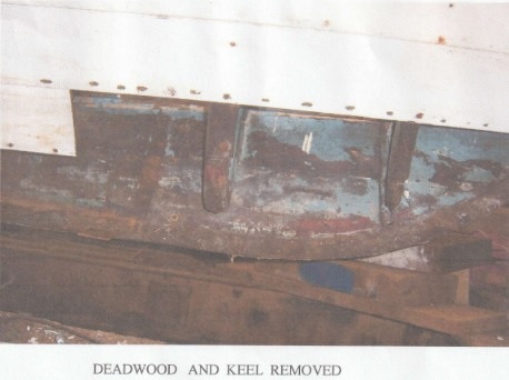
Now the challenge starts, taking off some plywood patches on the keel section forward, we discover a terrible attempt at repair. This involves a short piece of timber fit right through the keel, with no bolts in, held in only by the ply wood. After we remove the keel repair we discover that this was only the Beginning as the deadwood was very soft. The attempt at repair was only making things worse as the keel section forward of this was a bit worn. The decision to replace the forward Section was taken.

Keel Section Repair -No bolts, just tapped out
Page 7.
Repair to forward Deadwood and Keel Section.
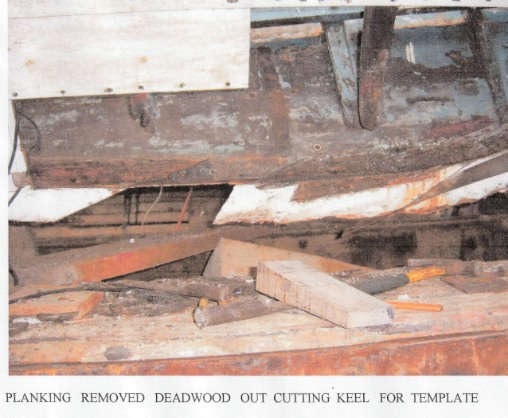
When a replacement of a deadwood is required, you can reduce the fitting time and make the fit more precise by biting the bullet and removing planking on the keel strake and no. 2 plank.
I remove about 4 feet of the 2nd strake then about 5 feet of the keel strake, with the no 2 plank removed, the access to the nails and fixings in the keel strake is greatly improved.
Once both planks are off we get a true picture as to the condition of the deadwood. Things are not looking good the forward section is rotten and the “Golden rule in boat restoration – if rots about get it out” this can only cause problems in the future, the big decision how far, Mick decides take out the full stem and apron.
With a new coble the stem and apron are in one section of timber but with a repair its easier to fit these in 2 sections and bolt through a much stronger job as you can avoid short grains on timber ends.
Page 8.
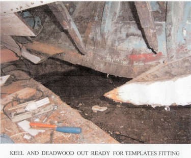
Making the Templates.
When making up templates its worth spending the time to get a good fit, as trimming off 1/2 inch softwood is much easier than taking down 3 inch oak.
Make up your template, keeping in mind the position of the scarf joints and position of bolts, a quick tip is to mark out in chalk first until you’re happy with position, then make up in timber.
Try to make up as many of the templates as you can. With all the templates made you can place them on the log and judge the cutting out. The advantage of this is, the saving of timber and avoiding short grains. These templates are not the ultimate size if you need to move the scarf a few inches to get it out, do so, it can be allowed on the next template.
When you cut out the sections sometimes it’s not possible to get the saw to exit the timber. A good tip is to bore a 1 inch hole in the waste wood this allows you to turn the log on the table and change the direction of the blade safely. The more holes the better but remember you could use some of the offcuts.
During the cutting out, keep as close as you can to the fit line but leave some on the waste side as during the cutting out the log can de-stress and change shape slightly so you might need to make a second cut on the fit line.
Page 9.
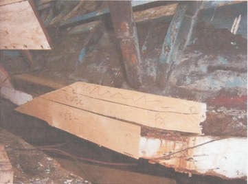
Note the template for the deadwood is made before the keel section is cut out.
Page 10.
With the forward base section the keel in place, we then fit the knee or deadwood on top planning the position of the through bolts for more maximum strength, also made and fit is an anchor chain fixing eye this is welded onto a plate that fits aver two of the through bolts instead of washers a much stronger job and no chance of breaking loose.
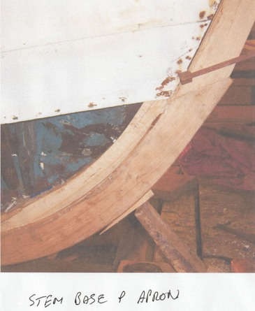
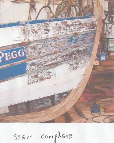
Next stage fitting the base section of the new stem, no template to make as we had the original to copy from rotten hut still in one piece. Next the upper part of the new stem post again a copy of original, now we fit the apron this is broader than the stem and when bevelled to the right set gives the landing area for the hull planking. The apron is made longer than the top stem section to keep the scarf joints apart for more strength.
Now its time to replace the forward planking removed to make easy repairs, hut before fixing a coat of paint is applied to the stem and apron. This is the only time they will get paint. Not exposed once planking done. Final touches, caulking along the keel seam on new planking and putty up the seams then a coat of grey primer.
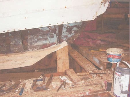 Figure 1: Peggy-Deadwood | 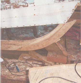 Figure 2: Keel Base and Lower Apron, Lower Stem Piece |
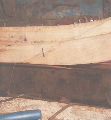 Figure 3: Note top section longer for joint strength. Bolts through anchor plate. |
 |  |
We now plan out where to start next and we move onto the transom.
Page 11.
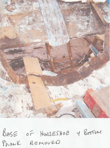
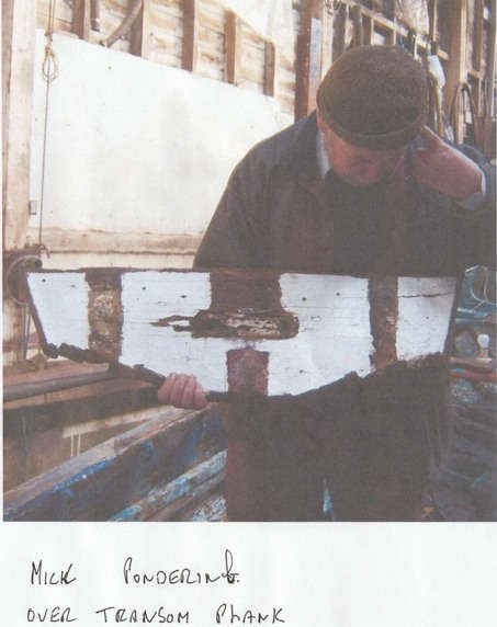
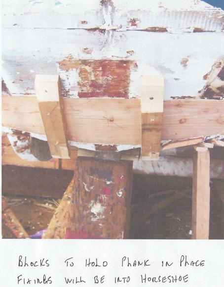
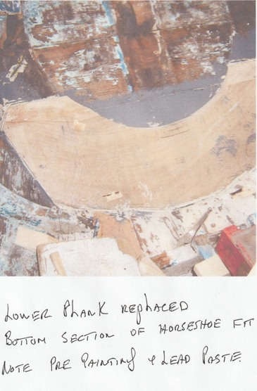
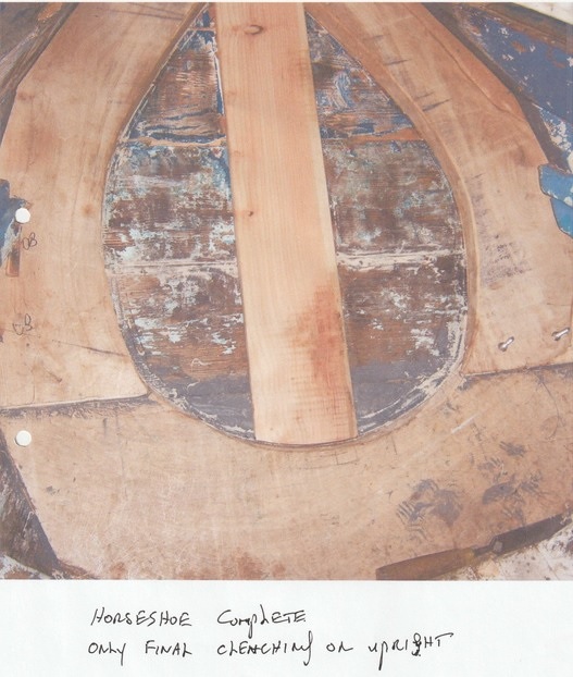
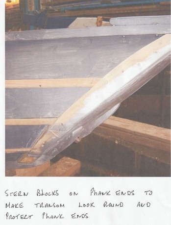
The transom or stern-back is made very strong as this has to take the lower rudder fitting with such a long rudder when put hard over the force is extreme hence the long tiller for crew to handle the load . This consists of 3/4 inch larch boards on the horizontal then a 3/4 inch larch board upright with copper clenching on every cross joint, the hull to planking has a 2 inch oak frame cut to shape this is called the horseshoe because of its shape, the lower section is about I inch wide oak with the sides reducing to 6 inch at the top.
When fitting the boards they must be fit from the inside due to the angle of the hull planking when fitting the base section of the horseshoe the top edge must be cut with a lot of bevel, due to the angle of transom if it was cut square to the hull this would cause a water trap and cause rot to happen on the long term again paint back before final fit, being at the waterline, this is also bedded in with a white lead paste. Put plenty on to ensure a water tight fit better to much than not enough you can clean up the excess and put it back in pot. Don’t waste it.
Now the side wings make a good template remember its 2 inch thick so put some 2 inch blocks on first to make template for where the front fits, if you don’t do this when you remove the back bevel to fit hull the timber will be under size, yet again paint before final fit. If you have to use two pieces to make the shape make the joint over 6 inches. This will give more room for fixings.
 |  |
 |  |
Page 12.
The Hull Planking.
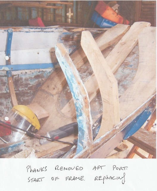
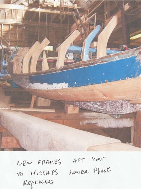
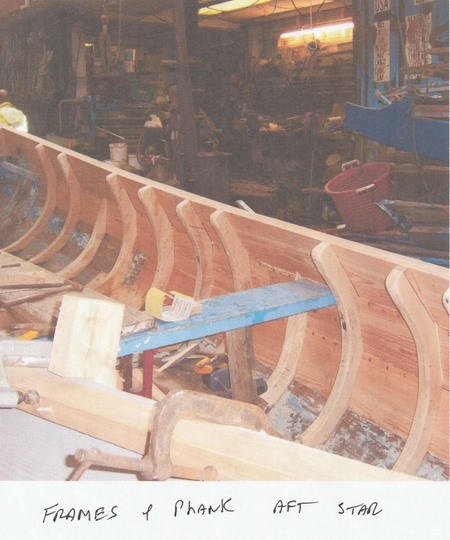
Now we start removing the planking on the aft port section, taking great care to preserve the best template for the new plank, also to not damage the frames that need replacing, again good templates. These frames are replaced in oak and ash according to what timber we have to get the best grain.
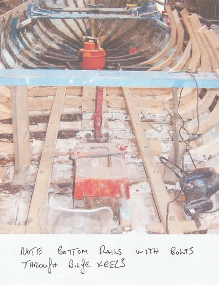
The frames base lands on the lower gross frame. These are usually about 3 inch thick, much stronger, the reason being that the outside bilge keel will have through bolts to hold it in plage and an inside rail which settles on the frames above and the same length of the bilge keel this puts all the strength into the bottom of the vessel when all the bolts are in.
This creates a big clamp effect, keeping all the frames in plage, the frames at the base joint will have copper clenching in them but on the planking usually at 6 inch galvanized nail this is cut with an inch showing through then bent over into the frame with a man holding a big hammer on the outside. A good tip is to use a 1/4 inch drill to create a grove into the frame to take the bent over section this will allow the nail to be below the frame surface and a bit putty to tidy up frame face.
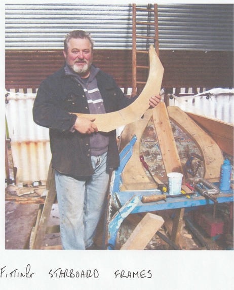
Several frames are replaced and primed.
 |  |
|  |
Page 12B
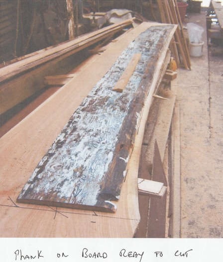
Next we place the plank templates on the new Larch planks. Always gut the planks to shape before planing this leaves the offcuts thicker for use elsewhere.
Always leave some length on the planks if you have a problem with the scarf joint you can correct and move the plank along and cut the excess off when fixed to transom.
When fitting the top plank leave at least 1/2 inch on the top edge this will have a bevel on the top edge if you cut it exact it will get damaged when fitting the gunwhales it will be planed off when the gunwhale is fixed then a 2×1 and a 1/2inch chafe rail is fit to protect the plank, if it’s a working coble this top rail gets a lot of wear off the pot ropes and nets but is easier to replace than a gunwhale.
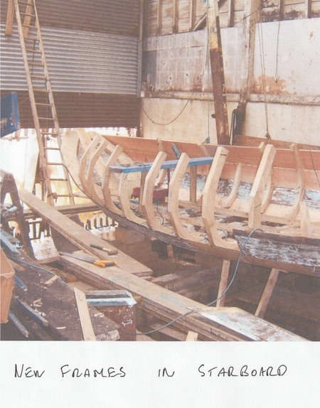
On the starboard side several frames and planks are replaced using the procedure as for port.
 |  |
 |  |
Page 13.
The Gunwhales.
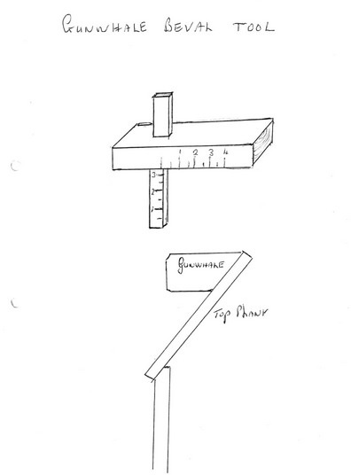
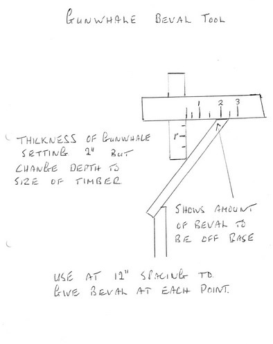
Depending on the size of the vessel these vary in thickness and width on the larger Yorkshire working vessels could be 5 inch by 3 inch but on the Peggy being a sailing coble they are much lighter at 4 inch by 2 inch, the top plank has a lot of tumblehome “means leaning inboard at top” this means a lot of bevel has to be removed to bring gunwhale flat at top, you can make a tool to help you determine this, rather than write a description a drawing and how to use accompany this page, but this can also be used on other parts where needed.
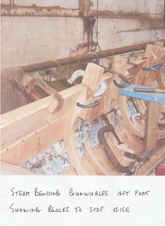
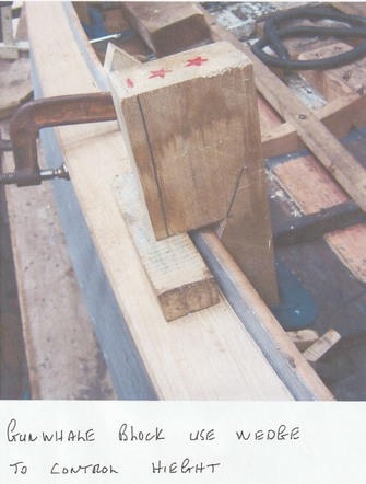
When fitting the gunwhales try to stagger the lengths on opposite sides of the vessel to give more strength, paint top 3 inches of plank and back of gunwhale before final fix. When steam bending the gunwhale timber is very difficult to set the cramps square, so to correct this we gut a block that will be square to the outside edge of the timber and cramp this to the frames inboard.
The base of this block is also square to the top of the timber this allows for the holding down position. If you don’t do this, due to the bevel on gunwhale, it will just keep rising up and jumping off the plank. See photograph for use of blocks. Don’t forget to leave length on the gunwhale timber to fit scarf joint, also on most cobles these extend past the transom to take the scut fixed on gunwhales across the back and above the transom. These often referred to as the horns.
When fixing the gunwhale the usual method is to drill the frame tops right through to take a 6 inch galvanized nail, but these are put in with the nail head on the inside this gives a stronger hold on frame top and will not split frame head top. On the outside these are plated over. Do the same with the drill as on fixing frames to sink the nail below surface. Don’t want any snags in way of net hauling.
 |  |
 |  |
Page 14.
The Aft Scut.
This is a broad piece of oak usually 2 inch thickness about 16 inches wide, it fits across the extreme back of the gunwhales and has 3 bolts through the gunwhales on each side, the reason for such a strong job is the pin for the rudder passes through this the coble rudder is usually quite long and about 15 inches wide this takes a great deal of strain and has a long tiller to allow the crew to hold it in place. The edges above the gunwhale are tapered and rounded down.
In the middle in front of the rudder pin hole there is a 2 inch hole through, this is for the aft mooring rope, the rope passes through to a plate with a ring welded on held in place with 2 bolts these bolts are through the base of the horseshoe and on the outside of the transom the bottom ring plate for the rudder.
The hole for the rudder pin should also have a stainless plate around it about 8 inches square with a 2 inch bend down the transom this is to protect the scut when shipping the rudder in and out.
Page 15.
Listons or Landing battens.
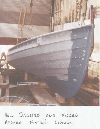
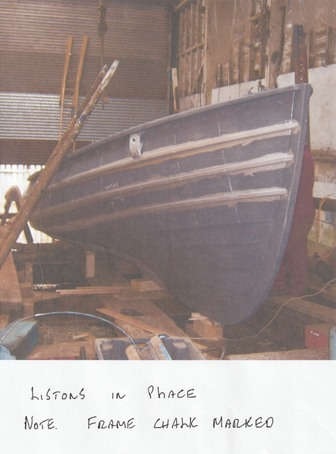
Geordies prefer the name listons these are a hardwood rail that fits on the bottom edge of the planking and are made thicker than the planks, these act a protection for the plank edge from ropes, pots and nets, much easier to replace a liston than a new plank and these are usually about 1 and 1/2 inch x 1 inch rounded off on bottom the top edge just a corner off with the hand plane, some bevel off the top edge to fit the planking but each liston has a different bevel so dress each one and mark for location but try to stagger the joints, these will be fixed with a galvanized nail through the planking and into the frames this gives even more strength to the hull.
When all are ready find a place to give them two coats of paint, paint a strip of planking about 3 inches including the bottom edge of the plank above before fitting.
If not already done now is the best time to fill in the planking nails usually putty, and sand down to finish with the listons fit its difficult to get the sander in, but don’t paint yet as you need to see frame nails for fixing the listons.
 |  |
 |
Page 16.
The stern tube.
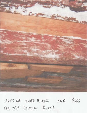
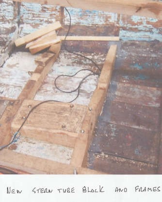
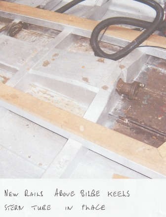
These had to be replaced due to rot in the timber. The blocks are made up in oak between 2 frame spaces and through bolted, the forward bolts will have pads on them these cover 2 frames on the underside of hull. The outside block covers 2 frames through bolted these will have pads on the inside. The forward frame is made thicker and wider to take the face plate of the brass stern tube. This also gives better fixing as it is not end grain. This is reduced at the frame ends to match the existing frames.
When fitting the block we try to match up the existing bore hole on the bench this helps keeping things in line on the final bore of the tube.
 |  |
 |
Page 17.
Now we start to refit the thwarts and fit the new knees these are cut with care to get the grain right. If not cut correctly these will fail at the short grain section. These will be fixed through the gunwhale as other fixings, with galvanized nails.
The working boats tend to use steel knees 2 inch x 1/2 flat bar with a 3/4 inch round bar welded on to form a triangle from gunwhale to thwart, this gives a very strong job and also the bar gives a tying up point for ropes fenders etc. The midship thwart on the larger boats usually has a bulkhead constructed on the aft edge this adds some strength but also creates a separation from the engine area and the working area.
The thwart midships and next forward usually have a plywood board resting between them this creates part of the engine cover also makes getting forward much easier.
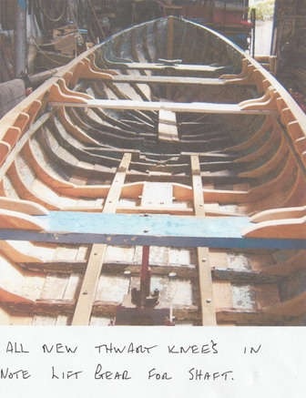 | 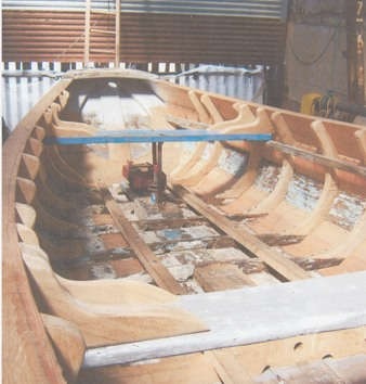 New knees and scut fitted to transom top |
Page 18.
Deck floors.
Next job to start is the floors and beams, we start by putting in the long beams these stretch from the base of the horseshoe to the engine beds, location is above the inside rail that holds the bilge keels, with such a long spread you will have to put in three uprights to support the load these will be cut to fit on and be fastened to a frame. Make sure that the timber comes short of the hull planking, reason being if on the planking a heavy load on the floors could push the planking away from frame causing a leak.
With beams set we now do the inwires, these are the rails that run along the frames to support the floors on the outside edge. To get the correct height for these place a straight edge on top at the beams and mark the height on the frames, this will be about 2×1 inch due to the position on the frame the top corner, will need a lot of bevel off for the boards to lay flat normally about 3/4 inch is needed but don’t fasten in until the bevels are checked. You can’t take more off once nailed as this will make it to low. On the top of the main beams fix a lath 3/4 inch x the thickness of floor boards this gives the final position of hoards on beam.
With everything set off we now start on the boards the best way to do this will he to do the center boards first this will give a good working area to work from when fitting the sides. A bit more skill needed to fit the side floors as these run around the hull frames fit the boards but leave length on until the fit is right.
As the underside will need a lot of bevel off correct this later will make the boards short.
Don’t make the boards to good a fit to frames, this will give any water a chance to escape the deck floor.
Page 19.
With all the timber work done inside we now have to work out a painting plan, we don’t want to be held back with wet paint, so first job clean out inboard the place in some temporary boards and start the first under coat grey. A good tip is to have a bit putty to hand and any bits needing filling can be done as you go along, take the undercoat below the floor level, the final cut in will be done with the black varnish.
Black varnish or bitumen paint is the best for the job below floors as it seals up any holes or splits but mostly because it prevents any rot. This is usually left till the gloss has been done on inside you can paint bitumen over gloss but you can not paint gloss over bitumen.
How we move to the outside, a good rub down with the sandpaper then a full undercoat down to 5 inches below water line.
Back inside second undercoat this time the whole boat with the grey back outside mark off the water line and the transom ring, some boats just have a straight water line hut the tradition is to have the ring in a white band this matches the water line aft then rises in the middle.
Back outside this time the gloss blue this is the part of the job I love the transition the gloss makes is very rewarding, next undercoat the white flash forward and the transom ring.
The next dramatic change is the sign writer a Mr. Paul Robson from Whitley Bay, a true master at his craft. He puts on the name, the boat numbers and the owners name in bold letters with shadow effect.
Back inside a few jobs to do some repairs are needed on the inspection box aft. This is a hole through the boat aft to gain access to the propeller if a rope is fouled at sea, this is made so the height of the box is above the water line. If you have to do this at sea you must take care in case of any swell as when the boat dips aft it will allow water in, it has a plug made to fit and a rubber gasket to seal down. This plug is made a good fit with base level with outside planking. If this is not right it will act as a sound box, sounding really bad with power on. It can also cause cavitation, reducing the power of propeller.
Forward, being a sailing coble it has a mast box on the forward thwart some minor repairs done.
Next paint bitumen under the engine bay and fit the new bed plates. And refit the engine.
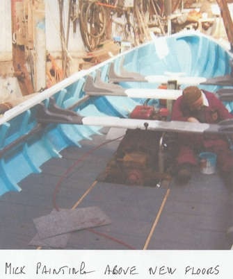 | 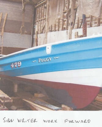 |
Page 20.
With the engine now in place we connect up the propeller shaft and put in new gland packing and grease up.
The propeller and shaft on this boat is unusual and becoming quite rare, it is designed to be lifted up between the bilge keels when the boat is beached, but also to reduce the drag effect when under sail the propeller is also unusual as it only has two blades enabling it to gain maximum height between the bilge keels.
Just to the front of the inspection box there is a stern gland installed in the vertical position the shaft through this has 2 holes drilled through for the 2 positions raised or locked down when in use.
To make this work the lift on the outboard propeller shaft close to the gland there is a universal joint then a second shaft goes into a swivel bearing on the end of the upright shaft. This works well and is a proven design, only problem it can rattle and vibrate a bit when in use.
Page 21.
Now its time for a change in material. It’s iron work we need with the help of our faithful stove and the gas torch its making the sailing gear and the rudder fittings, lots of heat, the anvil and big hammers.
We make three large sailing hooks, two fixing points and two shroud plates.
Two plates to fit on the rudder with long pins, these are always about 9 inches long the reason being you don’t want the rudder to jump out the eye plates in bad weather. A plate for the bottom pin to fit through will be bolted through the base of the horseshoe and on the inside of these bolts a plate with a ring welded on to take the stern mooring ropes.
The top pin on the rudder goes through the back edge of the oak scut.
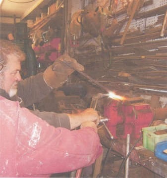 MD being taught ironwork – the basics. | 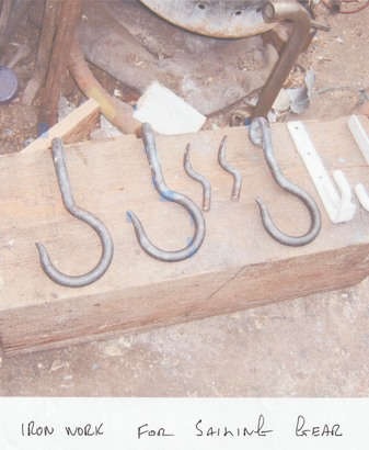 |
Page 22.
Back on the painting this time its the white gloss on the waterline and the stern ring, the first coat of anti fouling paint put on not the easy job crawling over the cradle but has to he done.
Another day and second coat of anti foul applied. Now the outside is complete and the visitors now come in to make their comments but its all praise a difficult thing for some to do when the mouth is full of words they had to eat, but just look at the smile on Mick’s face well worth the effort says he.
Mick escapes to the marine trust next door while we start the clean up ready for the big day going down the slipway into the Tyne once again, but Mick’s not hiding he’s preparing the sail and preparing the ropes eager to get sailing and see what she does and how she handles.
Page 23.
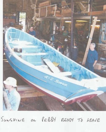
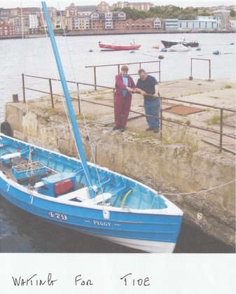
Well the long awaited day is here the Peggy is ready for the water, it’s a good day dry and a gentle breeze with tide just after lunch.
We lower the boat down the slip nice an easy, just as we leave the boatshed bright sunshine cascades over the glossy new paint a perfect photo shot.
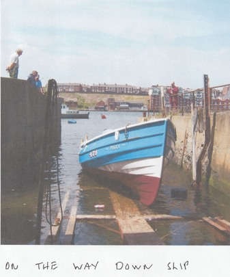
When we reach the half way point on the slip we stop and Mick starts work on the mast lifting and setting the ropes, we connect the bilge pump to the batteries. When a boats been out the water for some time they always take some water until the planks swell, better to be ready just in case.
The tide has come up now and all’s ready, so down with the cradle the last few yards and she’s afloat and looking great. Quite a good turn out to see her in all her glory, a proud moment of satisfaction for me. This makes it all worthwhile doing a job you love and being able to say I did that.
Saving a bit of history as well.
 |  |
 | 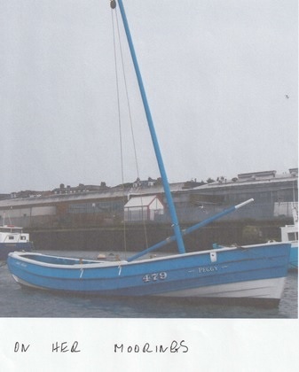 |
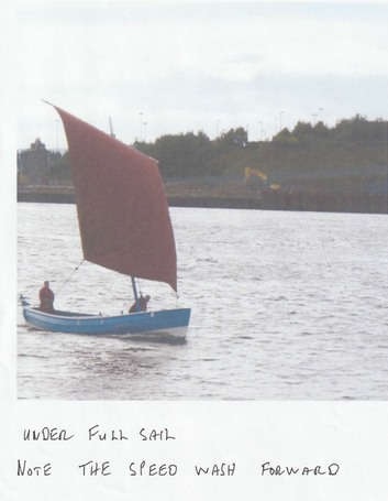
Now she’s clear of the slip headed upriver then turns about to catch the wind the sails hoisted and the Peggy’s off like a race horse, the sail is full the suns shining on her, Mick on the tiller thinking where’s the brakes are we breaking the port speed rules? a pull on the ropes to adjust the trim then drop the sail to turn about and head upriver again.
We now have lots of people watching the boat including the doubters and the “it will never be done squad” but now they have to watch this glossy piece of history saved go sailing past, this time much closer to the quayside and Mick is waving to them, but it appears that he’s hurt his hand as he’s not using all his fingers to wave at the doubters.
Well it’s off for a run about the harbour for Mick and his son leaving us to pull up the cradle and have a few days off, just a few, as by the end of the week there will be another coble on the cradle this time the coble Morning Harvest from Blyth, a bigger boat with a lot of work and a new engine, the main difference this one will be red not blue.
Well I hope this will be of interest and helpful to anyone trying to restore a coble and you enjoy the task as much as I do. I apologize for any grammar or spelling mistakes I am a boat builder not an author if the paper was wood and the pen copper nails it would have been a better job.
Good luck to all,
Fred Crowell
With thanks to Mick, his son and my number one helper, Alan Woods